
Chip resistors are commonly utilised in various NASA projects, but instances of alumina substrate cracking during environmental testing are exceptionally rare. Recently, two occurrences of thick-film chip resistor cracking were documented during thermal cycling following vibration testing. The fractures were observed along the short axis of the resistors, primarily attributed to bending. Analyses conducted ruled out defective production lots and fatigue as potential causes, instead highlighting factors such as board flexure, the orientation of components, excessive solder application, and mounting stresses as significant contributors. To mitigate the risks of flexure-induced cracking in ceramic components on printed circuit boards, it is recommended that careful placement of components, finite element analysis, controlled solder fillet height, thorough inspection, and functional thermal shock testing be undertaken.
Historical Context of Chip Resistor Failures
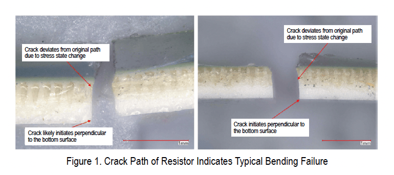
The NASA Engineering and Safety Centre (NESC) has noted a historical lack of reported cases concerning the cracking of chip resistors’ alumina substrates during vibration and thermal cycling, despite the widespread use of these resistors across NASA missions. The two recent incidents involving thick-film chip resistors were observed during environmental acceptance testing conducted on printed circuit board assemblies. Both failures transpired during thermal cycling after vibration testing, leading to intermittent open circuit failures at elevated temperatures, which restored functionality at ambient conditions. The fractures occurred at the mid-span of each resistor, running parallel to the terminations. Notably, both resistors were situated in similar locations close to the edges of two identical circuit boards. The cracks in the failed resistors were oriented along the short axis, indicative of bending forces, with no signs of pre-existing defects detected.
Investigation of Causative Factors
Initial hypotheses suggested that vibration-induced damage may have affected resistors from the same production lot. However, extensive testing confirmed that the resistor lot complied with the procurement specifications outlined in MIL-PRF-55342, with no evidence of defects detected. This comprehensive analysis indicated a lack of increased risk associated with the production lot in question.
Independent failure analyses determined that the cracked chip resistors experienced bending and tensile failures. No definitive root cause or visible defect was identified at the crack initiation site. Both resistors exhibited a singular, straight crack across the short axis, perpendicular to the long axis, reinforcing the conclusion of a bending or tensile failure without any twisting involved.
Contributing Factors and Design Considerations
The damage patterns observed do not align with cyclic fatigue, thus making fatigue failure during vibration an unlikely cause. Optical and scanning electron microscopy analyses conducted by NESC did not reveal any flaws that could indicate fatigue damage initiation and progression, further supporting the notion that defective components and fatigue-related issues were not the root causes.
While no direct root cause was identified, several contributing factors were recognised that necessitate increased design consideration for large footprint ceramic components situated near the edges of printed circuit boards. These factors may lead to stress cracks arising from manufacturing or installation-induced bow or twist in the circuit boards, and include:
- The positioning of relatively large resistors (case size 2512) adjacent to the board’s edge with their long axis aligned parallel to the card edge, thereby heightening susceptibility to damage from board flexure.
- Overabundant solder extending onto the top pads of the resistor terminations.
- Excessive bending moments or loads resulting from board bow or twist during installation.
- Rigid mounting of the board to a fixed frame, which may store and amplify bow or twist stresses.
- Inadequate fastener torquing patterns, which could concentrate mounting stresses specifically at the resistor sites.
Recommendations for Component Assembly
Given the recent findings, the following guidelines should be considered when assembling ceramic body components onto printed circuit boards:
- Component Orientation: Avoid aligning the long axis of large footprint ceramic components parallel to the edges of the printed circuit board to minimise susceptibility to both global and local flexure damage.
- Finite Element Analysis: Conduct sufficient finite element analysis to ensure adequate stress and displacement margins for large components when located near the board’s edge.
- Solder Joint Fillet Limits: Keep solder off the top surfaces of terminations. Excess solder can create a rigid joint that transmits flexure from the printed circuit board directly into the ceramic, increasing the risk of cracking. Consult individual component manufacturers for specific solder fillet height limitations.
- Solder Joint Inspection: Carry out inspections of solder joints or review photographic evidence to ensure components possess sufficient, but not excessive, solder fillets in accordance with manufacturer specifications.
- Functional Thermal Shock Testing: Implement one to three thermal cycles, including a hot-dwell functional test, prior to vibration testing to assess the integrity of components as assembled.
References
1. MIL-PRF-55342 Resistor, Chip, Fixed, Film, Nonestablished Reliability, Established Reliability, Space Level
2. MIL-PRF-55342/9 Resistor, Fixed, Film, Chip, Nonestablished Reliability, Established Reliability, Space Level, Style RM2512
3. MIL-STD-202 Method 218 Board Flex



More Stories
Celebrating 65 Years of NASA’s Johnson Space Center: A Journey Through Time
NASA’s Hubble Space Telescope Discovers Missing Oxygen in Nearby Dwarf Galaxies
Explore November’s Night Sky: Your Guide to Celestial Wonders and Shorter Days